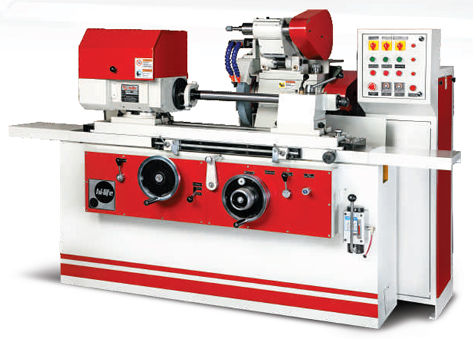
CYLINDRICAL GRINDING MACHINE
Cylindrical Grinding Machines have been designed to cater customer requirements of high accuracy, productivity and reliability of performance. These machines are suitable for producon and tool‐room applications.
SALIENT FEATURES
MACHINE BED
- Machine bed is of one piece, close grained, graded cast iron.
- Box Structure design, heavily reinforced with ribs, provides high rigidity and stability.
MACHINE GUIDE WAYS
- Machine guideways of V-Flat construction are precisely hand scrapped.
- Work head table and Grinding wheel slideways are coated with "TURCITE-B" linear bearing material which gives stick slip free movement, excellent vibration damping and high positioning accuracy.
- Continuous automatic lubrication provided for table guideways. Centralised lubrication sytem is also provided, for efficient and positive lubrication of other moving parts.
WORK HEAD
WHEEL HEAD
ELECTRICAL
HYDRAULICS
INFEED SYSTEM
- The machine has a rigid Universal Work Head, which can be swivelled to facilitate taper grinding.
- Work head spindle can be locked for grinding between centres or it can be rotated with the driving plate to carry work holding fixtures like chuck, collet or face plate.
WHEEL HEAD
- Wheel head spindle is made of special alloy steel, specially heat treated, ground and lapped to achieve high dimensional stability and long life.
- Spindle runs in precision Hydrodynamic White metal bearings, which give very high accuracy and excellent surface finish to the work piece.
- Hi-speed Cartridge type grinding wheel spindle with precision Antifriction bearings can be offered as optional.
ELECTRICAL
- Electrical / Electronic controls are contained in separate control cabinet, outside the machine, making it moisture proof and provides easy maintenance.
HYDRAULICS
- Hydraulic power pack with solenoid valves is housed outside the machine.
- Extremely good thermal stability is achieved in the machine by isolating the hydraulic unit.
INFEED SYSTEM
- Infeed system comprises of hardened and ground feed screw with dual support, which ensures high positioning accuracy and repeatability.
- Specially designed nut having backlash adjustment is provided.
- Automatic infeed at table reversal.
- Hydraulically operated Rapid approach/Retraction of Grinding wheel slide.
TAILSTOCK
DWELL
AUTOMATIC GRINDING CYCLE (Optional)
INTERNAL GRINDING ATTACHMENT (Optional)
OPTIONAL
RANGE OF OTHER MACHINES
- Tailstock is of single piece construction for maximum rigidity.
- Hydraulic Actuation & Micro Taper correction facility is optional.
DWELL
- Electronic dwelling arrangement provided for effective End grinding operation. Separate timers for left and right ends.
AUTOMATIC GRINDING CYCLE (Optional)
- Single button operated Automatic Plunge and Traverse grinding cycles.
- Cycle operates as: Work head & Coolant ON - Rapid approach - Auto feed - Spark off - Rapid retraction and infeed hand wheel turns back to starting position - Work head & Coolant OFF.
- Amount of infeed, infeed rate and spark off time are adjustable. Left /right / both ends feed selecon available during traverse grinding.
INTERNAL GRINDING ATTACHMENT (Optional)
- Internal grinding attachment (swing down type) with its independent drive motor is provided on the wheel head and can be quickly lowered into grinding position.
- Variety of Internal Grinding spindles can be offered.
OPTIONAL
- Hi-speed Cartridge type Grinding wheel spindle with precision Antifriction bearings, Work head with Anti-friction bearings, Variable Workspeed & Wheel speed, Inprocess Gauging system, Ballscrew for infeed slide & LM Guideways for Infeed slide.
RANGE OF OTHER MACHINES
- Centreless Grinding Machine - CNC/Hydraulic
- Cylindrical Grinding Machine - CNC
- Internal Grinding Machine - CNC/Hydraulic
- Robotic Automation for Grinding Machines